
Description
Module A-190-8 is a Midi/USB to Sync interface. The main application of the module is the control of clocked eurorack modules like sequencers, sequencer controllers, trigger divider, trigger sequencer and similar units. It may be used also to reset or sync LFOs or to trigger envelope generators with a fixed clock rate.
These are the most important features of this version of the module:
- Midi input (recognizes only Midi realtime messages clock, start, stop and continue)
- USB input for Midi via USB
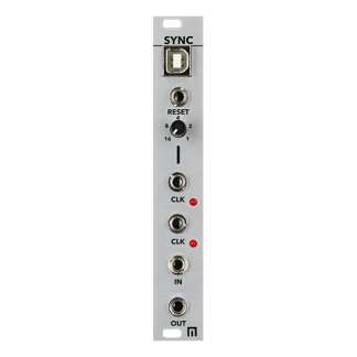
- Clock outputs:
- 96: outputs the Midi clock 1:1 (96 pulses per measure/ppm or 24 pulses per quarter note/ppq)
- 32: outputs the Midi clock divided by 3 (32 pulses per measure/ppm or 8 pulses per quarter note/ppq)
- 16: outputs the Midi clock divided by 6 (16 pulses per measure/ppm or 4 pulses per quarter note/ppq)
- 8: outputs the Midi clock divided by 12 (8 pulses per measure/ppm or 2 pulses per quarter note/ppq)
- 1: outputs a pulse at the start of each measure
- Other outputs:
- Start: outputs a pulse at each Midi Start or Continue message or generates a gate signal that remains in the high state until a Midi Stop message occurs (selectable via jumper)
- Stop: outputs a pulse at each Midi Stop message
- Reset: outputs a pulse at each Midi Start message that follows a Midi Stop message
- Wait control input, can be selected by means of a jumper between Gate function or Switch function: in Gate mode the positive edge of a gate signal is used to init the Wait state, in Switch mode an external switch that connects to GND is used to init the Wait state (equivalent to Switch-Trigger)
- Wait button / Wait control input: Whenever the Wait button is operated or a positive voltage is applied to the Wait input the module waits for the next measure start until the clock signals are generated.
- LED displays for clock, “1” and start (display of Start depends upon the chosen Start mode, see above)
- Output voltages can be selected between +5V and +12V by means of an internal jumper (for DIN Sync applications +5V has to be used !)
- Firmware updates via USB (provided that there will be updates available)
Technical remarks:
- In case that the inverted version of a signal is required the trigger modifier A-165 may be used.
- An internal jumper is used to define if the Start output generates only a short pulse as soon as a Midi start message is received or if it remains in the high state until a Midi stop signal is received.
- To control the sequencer modules A-155 or A-154 both versions will work because only the rising edge of the start signal is used.
- To control DIN SYNC equipment the “long” version of the start signal has to be chosen (i.e. the signal remains high until a stop is recognized) and the output voltage has to be set to +5V ! The +12V setting may destroy units equipped with Sync DIN sockets ! For this application a special cable with two 3.5 mm jack plugs on one side and a DIN5 male connector on the other side has to be made. For details concerning the DIN Sync specification please refer to our FAQ page.
- The meaning of the jumpers is described in this document: A190_8_jumper.pdf
Specs:
50 mA +12V
50 mA -12V
? mA 5V
6hp
50 mm deep