")
Description
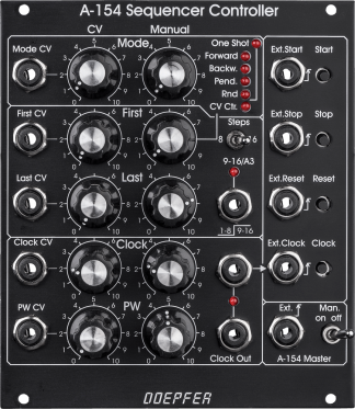
Module A-154 is a supplement to the A-155 Analog/Trigger Sequencer module. It offers a lot of new features that are not available in the basic control unit of the A-155. The A-154 is used to replace the control unit of one or two A-155, i.e. the section marked “Control” with Start / Stop / Step / Reset buttons and inputs in the upper left corner of the A-155 front panel. If the A-154 is used to control the A-155 the control section of the A-155 is put out of action.
These are the features of the A-154:
- Several running modes: forward, backward, pendulum, random, CV controlled step adressing. All modes are available as loop or one-shot.
- LED display of the 5 different current modes and one LED for loop/one-shot display
- Manual and voltage controlled selection (with attenuator) of the running mode. If no external control voltage is applied one of the 10 modes (5 modes x 2 loop/one-shot) is simply selected with a rotary knob. The CV input with attenuator is used to modulate the running mode with an external control voltage (digital high/low CV to switch between two modes or continuous analog CV to sweep through different modes). With the combination of manual control and CV with attenuator it is possible e.g. to use only two neighbouring modes (e.g. forward/backward) or sweep through all possible running modes
- Manual and voltage controlled selection (with attenuator) of first and last step of the sequence. The range is step 1…8 in 8 step mode resp. 1…16 in 16 step mode
- If the running mode “CV Controlled Step Address” is selected the First Step section is used to determine the active sequencer step. Consequently manual and voltage controlled selection (with attenuator) of the active step is possible: the active step can be set by hand with the first step manual control and then modulated by an external control voltage (e.g. LFO, Random, S&H, Theremin, Light CV source, Joy Stick) at the first step CV input (with attenuator).
- An internal voltage controlled clock generator with manual and CV control (with attenuator) is available. The output of the clock generator is displayed with a LED and is used as sequencer clock provided that no external clock signal is connected to the Clock In socket (normalled socket). If the CV input of the Clock section is connected to one of the analog outputs of the sequencer the time for each step can be set separately. Even jumps (or skipping) will be possible as we will introduce the feature that a very short clock pulse will be generated if the control voltage exceeds a certain value. For example the gate row of the A-155 can be used to obtain skipping of steps: the gate output simply has to be conneted to the CV input of the A-154 clock generator. If the corresponding switch of the A-155 is set correspondingly in the gate row the step will be skipped.
- Manual and voltage controlled (with attenuator) pulse width (PW) of the clock signal. This features can be used to obtain a different gate length for each step: e.g. one of the CV outputs of the A-155 can be used to control the PW. With a PW control voltage coming from a LFO/random/S&H the gate length will change automatically. CV coming from Theremin A-178, ribbon controller A-198, light controlled CV A-179, joy stick A-174 are other ways to control the gate length.
- 8/16 step mode: A toggle switch us used to select 8 or 16 steps. The “16 step” mode requires two A-155 and a voltage controlled switch A-150. The A-150 is controlled by the “A3” output of the A-154. This output remains “low” as long as the active step is in the range 1…8 and turns to “high” in the range 9…16. The A-150 is used to switch between the CV/trigger/gates outputs of the first A-155 (step 1…8) or second A-155 (step 9…16).
- If two A-155 are used they can work in parallel (8 steps) or serial (16 steps). The 8/16 steps switch determines if the 8 step mode (one A-155 or two A-155 in parallel) or the 16 step mode (two A-155 serial) is chosen. Both modes work with CV controlled step addressing too (see below). In 8 step mode only the steps 1…8 are addressed, in 16 step mode the steps 1…16. For serial operation an additional VC switch (A-150) is required – as mentioned above.
- The functions of the Start/Stop/Step/Reset buttons and inputs are the same as for the “old” control unit of the A-155:
- A high level at the Start input or operating the Start button starts the sequence from the momentarily addressed step. Not working in “CV controlled step address” mode.
- A high level at the Stop input or operating the Stop button stops the sequence (the last active step remains addressed). Not working in “CV controlled step address” mode.
- A high level at the Reset input or operating the Reset button resets the sequence to step 1. The sequence remains at step 1 as long as the Reset input level is high (function is activated by high level, not by low/high transition). Not working in “CV controlled step address” mode.
- A positive transition (low -> high) at the Step input or operating the Step button causes an advance to the next step. The step input is connected to the clock output of the internal clock generator provided that no plug is inserted to the step input socket. Not working in “CV controlled step address” mode.
- Manual and voltage controlled selection between “old” A-155 control or A-154 control of the A-155 connected to A-154 (A-154 master on/off function)
Remark: With the One-Shot modes the A-155/A-154 combination can be used e.g. as a complex envelope generator. The Gate resp. Trigger signal is applied to the Start input of the A-154. One analog row determines the levels of the envelope. The second analog row can be used to adjust the time length for each step. The Gate row can be used to select between smooth (Glide = on) or hard (Glide = off) transition between succeeding levels. For the One-Shot version of Random the sequence continues until accidentially the last step is addressed. Then the sequence stops. The combination of One-Shot and CV Addressed Step Selection is not available as it does not make sense.
Installation of the A-154: The 10 pin ribbon cable, that was used to connect the A-155 control section with the rest of the A-155 module has to be removed and plugged to the new A-154 sequencer controller. Therefore the A-154 has to be mounted on the right side of the A-155. In case that two A-155 have to be controlled the A-155 have to be mounted one on top of the other and the A-154 on the right side of the upper or lower A-155. Attention ! In case of two A-155 the second A-155 cannot be controlled by its “old” control unit. In this case both A-155 are controlled by the A-154 or the “old” control unit of the first A-155 (depending upon the position of the A-154 master switch).
For more detailed information please look at the user’s manual: A154_man.pdf.
Note: The function of the master switch is described in the wrong way in the user’s manual. In position “Off” the A-155 connected to the A-154 is controlled by the A-154, in position “On” the old control unit of the A.-155 is active.
Please pay attention to the notes that describes the connection of the modules A-154 and A-155: A154_155_Connection.pdf !
Specs:
Width: 22 HP / 111.4 mm
Depth: 80 mm (measured from the rear side of the front panel)
Current: : +60mA (+12V) / -20mA (-12V)